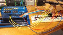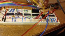

  (Breadboarded circuit and RC2014 breakout module) |
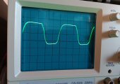
 (Output from the 100kHz. oscillator circuit that drives the counters) |
A few short months into exploring the world of RC2014 modules we were in a situation where we needed to time how long a certain piece of code took to execute. Our Easy Z80 board does not come with any built-in "clocks" to time events with. Sure it has some 16-bit counters running but they overflow within 100ms and would be useless for measuring anything practical. We also looked into the RC2014 RTC module and RTC chips, but they all only measure down to the second. We needed something with resolution down to hundreths of seconds. Enter this timer module project.
No, this isn't an official RC2014 module board and we have no plans to make it into one (maybe someone else will??). But, with this circuit any program, MBASIC or assembly, can measure time differences down to 1/100th of a second (measuring down to 1/1000th of a second is also easily done by eliminating the last frequency divider).
Once again, this is a project that is not particularly groundbreaking and can be easily duplicated. We utilized a SC115 Prototyping Breakout Module which offloads some of the address decoding logic for us (many thanks to Small Computer Central for their wonderful products).
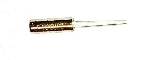
Our circuit starts with an oscillator circuit based on a 100kHz. quartz crystal and a couple of 74HCT00 gates. The output is then fed through three divide-by-10 counters to bring it down to 100Hz. Finally, the 100Hz. clock is fed to a wonderfully versitile IC: a 74LV8154 Dual 16-Bit Binary Counter, which is the final stage of the circuit and is what the Z80 interfaces with. With its two 16-bit counters cascaded, the circuit can measure times in hundreths of seconds up to 42,949,672.96 seconds, or ~497 days.
Sample MBASIC SDK for utilizing the circuit configured @ I/O addresses 0x08 - 0x0F:
			10 DEFINT M,P
			20 DEFSNG T
			100 GOSUB 2000 : REM INITIALIZE
			110 GOSUB 2100 : REM RESET COUNTER
			120 PRINT "DEMO FOR A FOX CONSULTING & DESIGN RC2014 TIMER MODULE."
			125 PRINT "PRESS 'P' TO PAUSE / UN-PAUSE DISPLAY."
			130 PRINT : PRINT "ELAPSED TIME:"
			135 PRINT : PRINT
			140 P = -1
			150 IF INKEY$ = "P" THEN P = -P
			160 IF P = 1 THEN GOTO 150
			170 GOSUB 2200 : REM TAKE READING
			180 PRINT CHR$(27);"[2F";
			190 PRINT MR4;MR3;MR2;MR1
			200 PRINT USING "#####.##    "; TT;
			210 S$ = RIGHT$("00"+MID$(STR$(TM), 2, 3), 3)
			220 S$ = S$ + ":" + RIGHT$("0"+MID$(STR$(TS), 2, 2), 2)
			230 S$ = S$ + "." + RIGHT$("0"+MID$(STR$(THS), 2, 2), 2)
			240 PRINT S$
			290 GOTO 150
			999 REM
			2000 REM ----- A FOX CONSULTING TIMING MODULE SDK ------
			2010 MBASE = &H8
			2020 RETURN
			2100 REM ----- RESET COUNTER -----
			2110 OUT MBASE + 5, 0
			2120 RETURN
			2200 REM ----- TAKE A READING -----
			2210 OUT MBASE + 4, 0
			2220 MR1 = INP(MBASE)
			2222 MR2 = INP(MBASE + 1)
			2224 MR3 = INP(MBASE + 2)
			2226 MR4 = INP(MBASE + 3)
			2230 TT = (MR1 * .01) + (MR2 * 2.56) + ((MR3 AND &H1F) * 655.36)
			2240 TTS = INT(TT)                   : REM TOTAL TIME IN WHOLE SECONDS
			2250 THS = INT((TT - TTS) * 100)     : REM TIME FRACTION - 1/100 SECONDS
			2260 TS = TTS MOD 60                 : REM TIME FRACTION - SECONDS
			2270 TM = (TTS - TS) / 60            : REM TIME FRACTION - MINUTES
			2280 RETURN