We purchased some BASIC Stamp development materials during the summer of 2006, but it wasn't until 2007 that we began to take a serious interest in these little gems. Not necesserily practical for use in mass production due to their price, speed and code limitations, for hobby work for beginners just learning embedded systems, or whenever you need something with a "brain" in a small space, these guys fit the bill. Sure, there are other alternatives out there (C Stamp, BasicATOM, ZBasic's ZX-24, or the Arduino), but none have the support base, both in protoboards or user support, that the Parallax BASIC Stamp did back in the 2000's.
This page is sort-of our lab notes for many of the BASIC Stamp applications we've made. We've put it up to aid others in their designs.
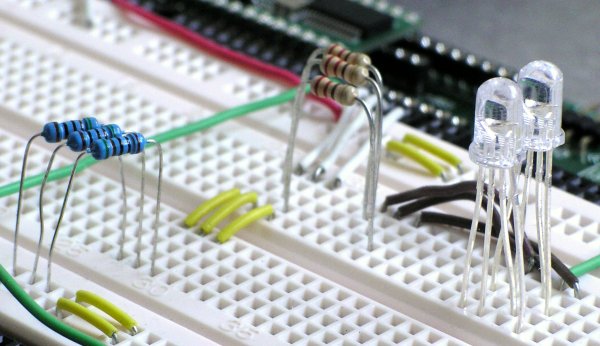
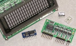 (Just a few components we bought to use with the BASIC Stamp) |
Our main development platform was Parallax's BASIC Stamp Professional Development Board which insludes a lot of built-in circuitry to make it easy to do prototyping.
Note that since the writing of this page back back in 2010, many of the external links have become broken. We do not have the time to activly maintain them.
| Stepper Motor Controller |
|---|
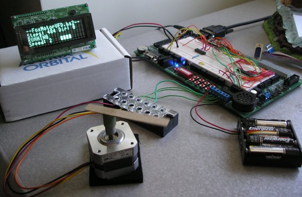
(FoxMotorVFD.bs2 in action) |
One of the first things we wanted to do with the BASIC Stamp was hook it up to a stepper motor. I think everyone wants to do this, don't they? Stepper motors are fun!
Anyhow, in addition to the stepper motor, we also picked up a nice 20 x 4 VFD display from Matrix Orbital which we also wanted to interface to the Stamp. So, if anyone is interested in interfacing their Stamp to either of these devices, this program might be of use to them:
FoxMotorVFD.bs2 program source.
We had the stepper motor coils wired to the L293D on the development board with the motor's external power source being a 6VDC battery pack. The VFD was hooked up to the development board's 5VDC power supply and the board's secondary RS-232 port, driven by a standard MAX232 driver.
Later on we purchased the Little Step-U Motor Controller to offload driving logic.
FoxMotor3.bs2 program source.
| Interfacing to Digitalker |
|---|
 (The entire DigiTalker circuit) |
 (The DigiTalker chipset + 74LS04 and 74LS595) |
I picked up a DigiTalker chipset way way waaay back in the late 80's, but until the BASIC Stamp I didn't really have an adequate environment to test and play with them.
The Digitalker's ~WR, ~CS and INTR lines were connected directly to I/O pins 3, 4 and 5 of the BASIC Stamp. A 74LS595 was connected to I/O pins 0, 1 and 2 and drive the data lines to the DigiTalker (we don't have a schematic but you can derrive the wiring from the source code documentation).
Once the circuit wiring was finished and after dealing with an issue with a missing inverter on one of the speech EPROM ~CS lines, I had the DigiTalker chips up and speaking in no time. It's fun giving old circuits new life. I used a MR-MINI-AUDIO module from Gravitech for the sound output as it is louder than the built-in speaker on the Parallax Stampworks Board.
Here is the DigiTalker.bs2 program source.
| SRAM Expansion Techniques |
|---|
 (Parallax's RAM Pack B module) |
Another one of the things we wanted to do with our BASIC Stamp was give it some more memory for mass storage--SRAM to be specific. Why SRAM? And why when you can get a Stamp 2e with 16k of memory? Because all that memory is EEPROM memory, and EEPROMs have a way of wearing out over time, and who wants to keep footing $50 for replacement stamps?
So, we seeked out Parallax's RAM Pack B module which used a commonly available SRAM chip. Unfortunately Parallax, for unknown reasons, had cancelled this product line (we were later able to find it being sold abroad here, and also from a place in Spain, who wants over $100 US for it--they're nuts!). Unable to acquire a SRAM expansion module we decided to investigate making our own using a bunch of different techniques.
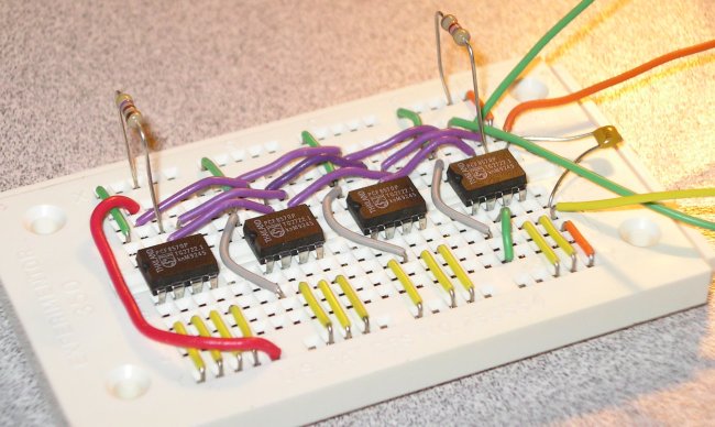 (4 x PCF8570's giving 1kbyte of SRAM) |
Our first attempt was to try using some PCF8570 I2C 256 byte SRAM chips.
This technique is okay if you only need a small amount of SRAM. It's small and only requires a 2-wire interface, but becomes impractical and expensive if you need more than 2k of SRAM (standard bus SRAM chips are cheaper per kilobyte than I2C chips), so we ventured on.
Here's the program source showing how to access the I2C SRAM chips.
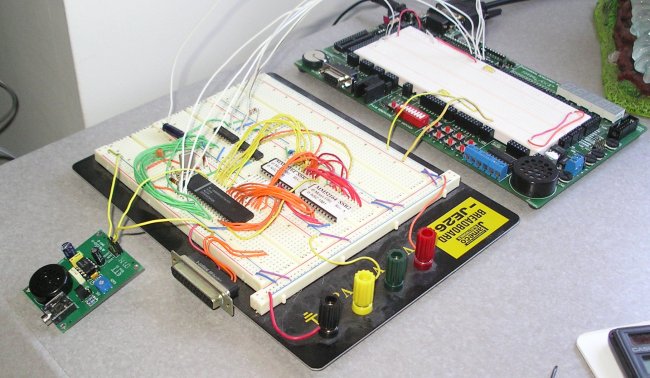
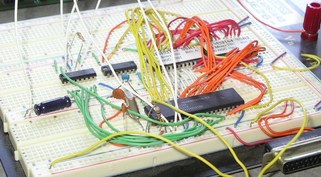
 (Schematic) |
 (Breadboardee circuit using a 7164 8k SRAM chip) |
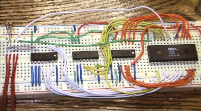
Our second attempt was inspired by something we stumbled upon while googling which involved serializing access to a standard SRAM bus chip via 74ALS299 8-bit universal shift registers. Apparantly we weren't the only people wanting to build a SRAM module.
We built the circuit and implemented it according to the website's outline. It worked great. It was screaming fast compared to the I2C version, even with a Stamp 2p. Of course the circuit is a lot more messy to wire up and requires 6 I/O lines from the stamp, but if you need 8k or more of SRAM expansion, this is the solution.
Here's the program source showing how to access the SRAM using the 74LS299's.
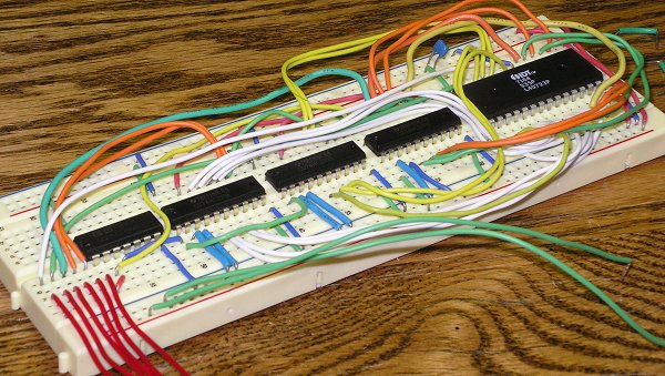
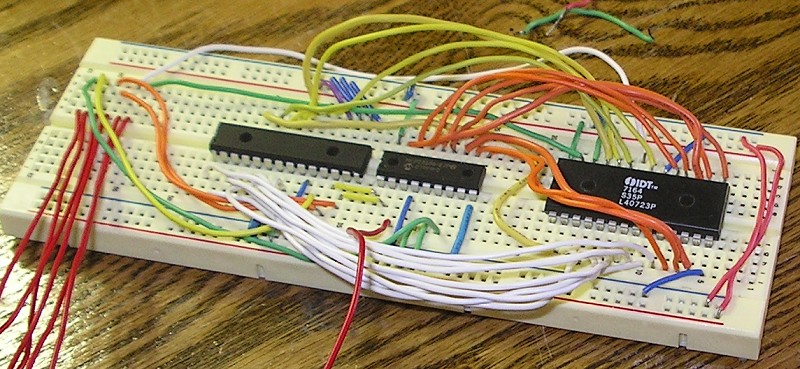
 (Breadboarded circuit using a 7164 8k SRAM chip) |
Still later on we were able to combine the I2C elements of our first attempt with the serialized access of our second attempt when we got our hands on some PCF8574 I2C 8-bit I/O expanders.
We wired up the PCF8574's similarly to how the 74LS299's had been and put the circuit to the test. To our surprise this circuit actually performed worse in our speed tests than our circuit with the 74LS299's! I guess even the Stamp 2p's SHIFTOUT and SHIFTIN beat its built-in I2C commands. On the plus side, the circuit is slightly less messy to wire up, and only 4 I/O lines are required from the Stamp.
Here's the program source showing how to access the SRAM using the PCF8574's.
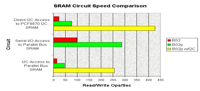
So, as you can see, each circuit has different advantages and disadvantages depending on the application required.
We've graphed out the speed performance for each of our solutions. We tested each circuit with a BASIC Stamp 2 and Stamp 2p24 with and without the 2p24's built-in I2C commands. The graph measures "Read/Write Operations", or the number of times we were able to write to and read from the memory chip per second. Since reading takes slightly more time than writing, memory read access would probably be about 2.5x the listed values.
|
And, when all is said and done, any of these circuits would probably be faster than the RAM Pack B module anyhow, since the RAM Pack B is a serial device whose fastest speed is 19.2kbaud.
 (Breadboarded circuit using a MCP23S17 and MCP23S08) |
We weren't quite ready to let this project go without a couple more tries! One thing that bugged us was that we weren't able to use the PCF8575 16-bit I/O expander to replace two of the PCF8574's in attempt #3 (the PCF8575 is only available in SOIC packaging so not breadboard-friendly). Of course there would probably have only been a 5% speed increase, but it would have been fun to try. Well, lo and behold we found the MCP23017 I2C and MCP23S17 SPI 16-bit I/O Expanders. We went with the SPI version mainly for speed and compatability, and re-built our 3 x PCF8574 circuit to use one MCP23S17 and one MCP23S08.
We figured the speed would be comporable to the 74HC299 circuit or at least a little faster than the PCF8574 one, and it was--just barely, but it turns out the MCP23Sxx chips are sort of a pain in the ass to deal with because of handling the enable and signal lines, passing address bits and switching the 8-bit port from output to input and back for each memory read/write. The speed was knocked way down, only yielding 35.31 read/write ops per second with a BS2, making it only about 1/3 as fast as the 74HC299 circuit, which, again, comes out as are streamlined winner. Some people praise the MCP23Sxx chips over the PCF857x ones and don't like the "quasi-bidirectional" I/O of the PCF8574/5, but at least I didn't have to keep switching the pin directions on them.
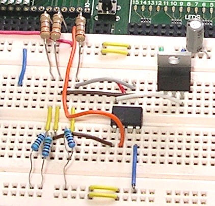 (Breadboarded circuit using 23K640 8k SPI SRAM chip) |
However, the ultimate solution arrived soon after we purchased the MCP23S17 as we discovered Microchip Technology Inc. also now makes SPI SRAM chips. What?? One chip? No shift registers or I/O chips?? Oh, come on, guys! Don't make it TOO easy! Okay, so the chip is a 3.3V system so we HAD to put in some resisters and a 3.3v regulator, but still! We used resister dividers (510 ohm and 330 ohm) to drop the Stamp's 5VDC down to 3VDC for the chip, and the chip's SDO line, operating at 0-3.3VDC is still enough level change for the Stamp to detect, so that was just directly wired to the Stamp.
Our 23K640 8K SPI-Bus Low-Power Serial SRAM clocked out at about 84 read/write ops per second, which (surprisingly) was slower by just a hare than the 74HC299 setup, but otherwise is the fastest (and simplest) solution. Plus, the 8k SRAM chips only cost $0.64 so it is also a cheap solution.
Okay, *NOW* I think we're done with the memory circuit ideas.
Back To Top| Temperature & Light Data Logger |
|---|
 (Slightly out-dated Schematic) |
|
|
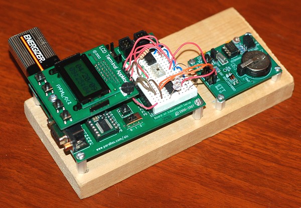
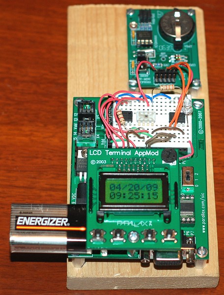
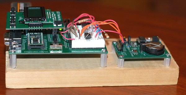 Pictures of the fully assembled Data Logger |
This project evolved from one of the very first programs we wrote for the BASIC Stamp. Over time more and more elements were added and the project grew into what it is today: an automated temperature and light data logger. This one projects incorporates more different hardware elements than anothing else we've done so far. If you are planning on writing a BASIC Stamp program that interfaces with any of these devices, this project should be of some help to you:
As I said, this project evolved and changed over time so our schematic was always changing. For example, originally we used a DS1307 SPI Real-Time Clock chip, as the schematic shows, and the LCD AppMod connections aren't even on the schematic (was added late in the game). We also added a nice blue LED that flashes while a sample is being taken. The four buttons on the AppMod work to: 1) Manually force taking a sample, 2) Dumping all samples to the serial port, 3) Clearing all samples from memory, and 4) Resetting the RTC to a known time. Because this project was constantly changing this is probably our least organized project.
As it works today, the data logger works very well: it takes readings every 6 minutes and can log temperature and light data for a period of around 25 hours before the EEPROM fills up, which is about the safe time a 9V battery source will last anyway. Results from our data logger have been imported into Microsoft Excel and have produced some very interesting graphs.
And, finally, here is the program source for our data logger. Notes on hardware revisions can be found right at the top.
| RGB LED Experiments |
|---|
 (An RGB LED) |
RGB LEDs contain three separate light emitters, one for red, green, and blue respectively. We picked up a load of these to play around with. Having the BASIC Stamp around made it easy to quickly explore all the color possibilities with these devices.
 (Schematic) |
 Breadboarded circuit) |
The first circuit we drew up gave us good basic color access to the LED. We could set each emitter to either full, half intensity, or off, giving a total of 27 possible colors. The setup is pretty simple, using just some resisters.
 (The seven basic colors of an RGB LED) |
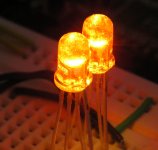 Mixing intensities gets you more color possibilities) |
Note that the LEDs we purchased were COMMON ANODE, meaning to turn an emitter on, we had to make the corresponding Stamp I/O pin LOW, not High. That's why the program's I/O pin levels might seem backwards.
The technique of doing half-intensity relies on the fact that if you set a Stamp's I/O pin to input, it's basically a passive connection only and voltage flows from Vdd through the LED, through R1, through R2, to ground.
The technique of doing full-intensity relies on the fact that if you set a Stamp's I/O pin to output LOW, it's basically a ground, and voltage flows from Vdd through the LED, through R1, through the Stamp, which is ground.
Turning an emitter off is just a simple matter of blocking voltage flow by setting the Stamp's I/O pin to output HIGH, eliminating any ground connections.
 Schematic for each cathode) |
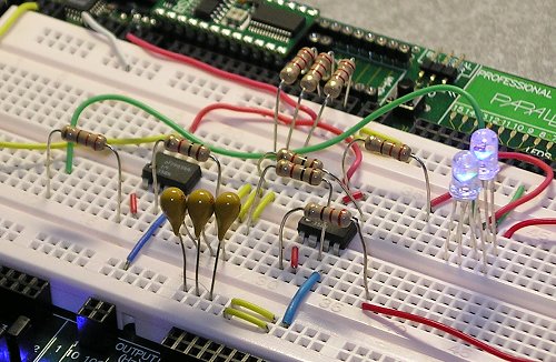 (breadboarded circuit) |
Oh, but we weren't quite done with these RGB LED's yet. It was time to make them slowly fade from one color to another. We accomplished this by using some LM358 op amps as voltage followers/buffers. The circuit for each cathode of the LED is shown here....
We also made a pretty robust fader program with a configurable preset pattern you could code in with delays and loops. Notice that we set different PWN sweep ranges for each emitter, because each emitter has different voltage requirements.
| RF Communications |
|---|
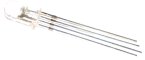
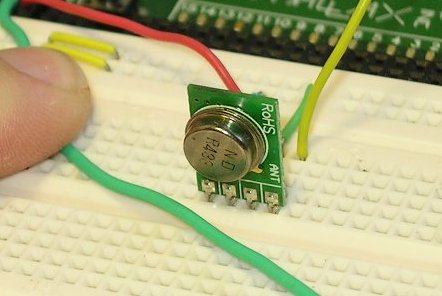 (Stationary transmitter) |
 (Portable receiver) |
We picked up a TWS-434A RF transmitter module, a RWS-434 RF receiver module and a couple of antennas from Reynolds Electronics and put them to work. Their website already had detailed plans for how to use their RF modules with the BASIC Stamp so we just keyed off of that when we did our experiments.
Program source for our RF transmitter. We learned that for reliable data communication we had to send at least four "junk" bytes to wake up the transmitter and get the receiver to synchronize with it.
Program source for our RF receiver. We built our receiver onto a BASIC Stamp Board Of Education so we could carry it around and test distance, and wired up a bunch of LEDs for showing packet receive status.
As you can see we also got a little fancy with our code and encorporated some very basic CRC logic to verify the integrity of our data packets. The code for the CRC came from the Parallax forums, I believe.
Getting good communication did require a little tweaking with the receiver and antennas. We got fairly good range (about 15-20 feet with no obstructions) with the modules even without any extra antennas. Adding a couple of whip-style antennas didn't do a *great* deal to boost performance, but we weren't able to do a lot of testing with them as we had other projects to move on to.
| Using the Modem AppMod |
|---|
 BASIC Stamp BoE w/Modem AppMod Circuit |
It took a fair amount of fancy footwork to track down and purchase a Parallax Stamp Modem Appmod board (yet another product Parallex inexplicably discontinued). The Modem AppMod board uses a Cermetek 1786 2400 baud Hayse-compatible modem. We wrote a very simple program to exercise the capabilities of the AppMod. The program let you turn on and off the different diodes in a RGB LED.
Program source for our Modem Appmod circuit.
We attempted to communicate with the AppMod via a USR Sportster 56k modem but had some connectivity issues where the AppMod would often pick up the line but never fully connect with the USR modem. This was likely due to the AppMod's low connect speed and the USR not being properly configured and "dummed down" to 2400 baud with no compression. This is, of course, no fault on the Modem AppMod's, and a stamp BoE + a modem AppMod all running off a 9V battary, able to respond to phone calls and allowing the caller to perform remote operations is a real dandy little trick and pleased us greatly.
| What about Basic Micro's BasicATOM? |
|---|
|
Early in 2009 we began evaluating Basic Micro's BasicATOM28-M, a faster and more powerful but much less known and even less supported competitor to the BASIC Stamp module. Two main features we liked in the BasicATOM were floating-point math and built-in string handling. Our initial experiments were very positive. At about the same price the BasicATOM28-M had gobs more memory and was about 8x faster than the BS2. However, we soon discovered why the BasicATOM line of products has not gained in popularity.
We downloaded the free IDE v2.2.1.1 from the website and the BASIC Atom manual v3.0.0.2 only to discover several inconsistancies between the two and the BasicATOM28-M itself where commands were documented yet either unimplemented or just non-functional--LCDINIT and ENABLEVIDEO, for example--commands which apparently were never finished (or purposly pulled) from MBasic Standard and will instead one day be implemented in MBasic Professional, which at the current is unknown whether it will be free or not. I guess we were suppose to downloaded and print their MBasic For Microcontrollers Manual v5.2 instead, which doesn't even include these commands. Wish we had known which manual to use with which IDE.
Command syntax descrepencies like this and buggy demo code combined with a confusing mix of different IDE versions and documentation, and lack of anything new from Basic Micro in many years has frustrated many users trying to evaluate the BasicATOM products (Example #1, Example #2). Parallax's BASIC Stamp may be slow and awkward to use for some applications, but it has a hell of a lot more support, both from Parallax itself and a giant userbase.
We haven't given up on the BasicATOM yet, though. We have invested in time and product and hope one day we'll be able to get working video from our module.